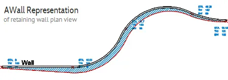
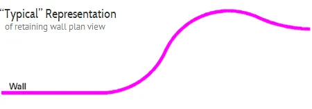
- Now include Crest and Toe Geometry
- Select Either Top of Wall or Bottom of Wall Baseline
- Plan Import to Vespa
- Accounts for continuously varying wall footprint along length of the wall according to wall height & batter (lean)
- Accurately shows the location of the bottom of wall
- Creates elevation views & quantities
- Instantly exports grading information to Vespa
- Designers guess at line thickness to represent wall width
- Does not take into account with increased wall height and batter (lean), wall width also increases
The AWall CAD Tool allows a user to accurately represent the Plan and Elevation views of a retaining wall on their grading plan. AWall takes into account the variable heights along the length of wall, wall batter, and wall width to generate a Plan view of the wall that will actually represent the “real” footprint of the wall.
No more guessing about the actual space requirements of your retaining wall or representing the wall with “nominal” line thicknesses – practices that often lead to disputes in the field.
Ideal For
Civil Designers / Landscape Architects
- Aiding in initial determination of Wall space requirements
- Generating “Real” Footprint of Wall on Grading Plan
- Elevation View Layouts
- Quantity Estimate of Wall Face Area for preliminary budgeting
Retaining Wall Designers
- Tracing existing Civil Grading Drawings for accurate gathering of Wall Geometry information to be imported to Vespa Design Software
- PDF Drawings can be underlayed in CAD (2010 or later) and traced
Learn more about using AWall CAD Tool
View TutorialsStart your 15 Day FREE Trial of Vespa2 MSE design sofware
Download Trial.